
Where it starts
Ballasted track is a floating system. The wheel load passes from rail to sleeper, from sleeper to ballast bed and from ballast bed to subgrade, and that chain only works as long as every sleeper bears along its full length. The vertical position of the track is not fixed: under repeated traffic loading the ballast bed settles, and that settlement is never uniform, even under an even load, and at transitions or insulated rail joints in the track large local settlements occur. Where the ballast locally sinks further than the rail can follow, the sleeper is left hanging. A void then sits beneath the sleeper, closing and reopening with every axle passage.
This happens above all where the stiffness of the substructure changes abruptly or where the track is locally loaded more heavily. The recurring examples are familiar:
- the transition from ballasted track to a bridge or other structure;
- the transition from ballasted track to ballastless track;
- the transition from timber to concrete sleepers;
- culverts or underpasses beneath the track;
- insulated rail joints or expansion joints;
- level crossings;
- crossings.
How uneven the distribution can become there is shown by field measurements on a section running over a piled culvert, with approach slabs between the structure and the embankment. Directly above those approach slabs, intended to soften the transition, the dynamic response was greatest. During a train passage the sleepers there moved vertically by up to around 6 mm, against roughly 1.5 mm on the adjacent plain line and 0.7 mm on the structure itself: a difference of a factor of 4 and more than 8 respectively. The settlement of the sleepers also proved 5 to 8 times greater than the movement of the ground beneath them, a clear sign that the sleepers were hanging from the rail. The differential settlement tilted the approach slabs, and the track began to see-saw around the stiff structure with every passage. That accelerated the degradation of the ballast bed and made the transition worse still.
Why it comes back
Laboratory research into the settlement behaviour of ballast shows that settlement under repeated loading can build up to 8–13 mm, depending on the state of compaction, and that the same locations settle again in successive maintenance cycles. That last point has an identifiable cause: the tamping machine itself.
Tamping restores the geometry well in the short term, but in doing so rearranges the ballast grains into a mechanically less stable packing. Under traffic the grains then seek a more stable arrangement, and that means fresh settlement, usually at or right next to the spot that has just been corrected. This behaviour is known as ballast memory: the bed remembers, as it were, where it sank before. The intervals between tamping runs grow shorter over time, while degradation of the ballast accumulates. Taken over the whole service life, ballast-related interventions account for roughly half of the total cost of ballasted track.
At transitions this process runs faster than on plain line. In some networks, transitions demand a maintenance intervention 4 to 8 times as often as open track. For a short transition section, of the order of 10 m, the usual approach means, time after time: mobilising a tamping machine and crew, reprofiling and often topping up the ballast, at least annually and frequently more often, with the accompanying track possession. The direct costs per location stack up quickly over the service life, quite apart from the indirect costs of reduced availability.
What a void does
The core of the problem lies in the void beneath the sleeper. Numerical simulations make the proportions visible. A height difference of around 5 mm at a transition drives the dynamic amplification factor from around 1.1 up to 1.8 with increasing speed. A void beneath the sleeper does considerably more: depending on its size and the train speed, amplification factors of 4 to 8 are calculated.
Very small gaps count too. Simulations of transition zones show that a void of just 1 mm already raises the contact forces between sleeper and ballast by around 70 percent, and that a 2 mm gap can increase the wheel forces by around 85 percent. The higher the speed, the more strongly these effects carry through, with transition zones as the places where the forces climb highest.
Every increased force has an effect on the bed: the impact grinds and displaces the ballast around the void, the void grows, and the next impact lands harder. The result is a self-reinforcing cycle of impact loading and degradation. Field experience and numerical models also indicate that such defects rarely stay local; they spread along the length of the track. Recent analytical research further shows that even well-designed stiffness transitions can degrade at an accelerated rate once loss of support concentrates the dynamic energy at a single point. A well-designed stiffness transition is no guarantee, then, as long as the support beneath the sleepers is not in order.
Measuring before the standard sees it
In common practice a transition is judged on the geometry at the surface: alignment and profile. Only when a standard value is exceeded does an intervention follow. By then the void beneath the sleeper has been there far longer, and the increased forces have already done their work.
It can be done earlier. Sensors on the rail or sleeper measure the dynamic response directly: accelerations, deflection patterns and the severity of impacts. Changes in these give away a growing void well before the geometry reaches the standard.
In the Netherlands this has been tested under real operating conditions in a monitored pilot with adjustable insulated rail joints on stiffness transitions, carried out by WeBoost and Kampa within ProRail’s SBIR innovation programme. Analysis of more than 40,000 train passages showed that elevated impact accelerations, and the sleeper settlements derived from them, were clearly detectable well before the usual geometry limits were exceeded, and that these signals consistently preceded accelerated degradation of ballast and track components at those locations. Once continuous support had been restored, the dynamic response demonstrably stabilised: the link between support and vibration excitation could be read directly in the measurement data.
Permanent monitoring is not always necessary. The monitored locations consistently point to the same risk zones: insulated rail joints, transitions and settlement-prone spots. That knowledge is directly usable for more targeted inspection and risk-based maintenance across the rest of the network.
The approaches side by side
- Tamping. The standard approach, and effective in the short term: the alignment is restored. The cause remains present, however, and ballast memory ensures the settlement returns, faster at transitions than elsewhere. Every tamping run demands machine deployment and a track possession, and wears the ballast bed further. As a structural approach for a transition, tamping therefore remains reactive.
- Addressing the subgrade and the structure. Transition structures try to soften the stiffness jump itself: reinforced backfills, approach slabs, auxiliary rails, geosynthetics and gradual stiffness transitions. Such measures can slow the deterioration, but field observations show that differential settlement and loss of support develop over time all the same. Whether the sleeper itself can help has also been investigated: laboratory tests and simulations with wedge-shaped sleeper undersides or under sleeper pads show peak contact forces 20–38 percent lower than for conventional sleepers, because ballast migrates more readily into any voids that form. These are chiefly options for new build or major renewal; for an existing transition they are rarely proportionate.
- Correcting at the fastening. The third route restores continuous support at the level of the fastening: a height-adjustable fastening corrects the rail height at the sleeper, so that the sleeper bears fully again while the ballast bed is left undisturbed. Corrections of up to 30 millimetres can be applied in steps, without major track possessions or specialised plant. Numerical simulations confirm the mechanism: removing the voids lowers the wheel-rail forces and ballast stresses considerably, even where the stiffness contrast itself remains. The effect grows with train speed: at 198 km/h the calculated peak wheel forces fell by more than half, from around 350 kN to 165 kN. If the subgrade settles further afterwards, small readjustments suffice. Experience from networks where this approach has been applied indicates that one corrective installation plus the occasional readjustment generally works out cheaper over the service life than repeated geometry-driven maintenance, certainly at heavily trafficked transitions. It also prevents fractures of insulated rail joints.
In recent research these routes are increasingly seen as complementary to one another. Differential settlement counts there as behaviour that will present itself regardless and has to be managed throughout the service life. That argues for transitions that are inspectable, adjustable and settlement-tolerant, so that intervention can be efficient whenever the measurement data call for it.
Where we come in
For the third route we developed ShimLift, a height-adjustable rail fastening that suits many types of sleepers. An adjustable wedge under the rail, paired with a counter-wedge, forms the core of the system; correction is possible up to 30 mm, which in practice is more than sufficient to eliminate the voids without calling in the tamping machine. ShimLift is applied at transitions to bridges and at level crossings, among other locations, and as support under insulated rail joints; we carried out the monitored pilot within ProRail’s SBIR programme together with WeBoost, and the system is in service in several countries. What that delivers is in essence what is set out above: a ballast bed that needs tamping less often, a longer service life for track and ballast, and more availability. How the adjustment works millimetre by millimetre, and which approvals apply in which country, you will find on the product page.
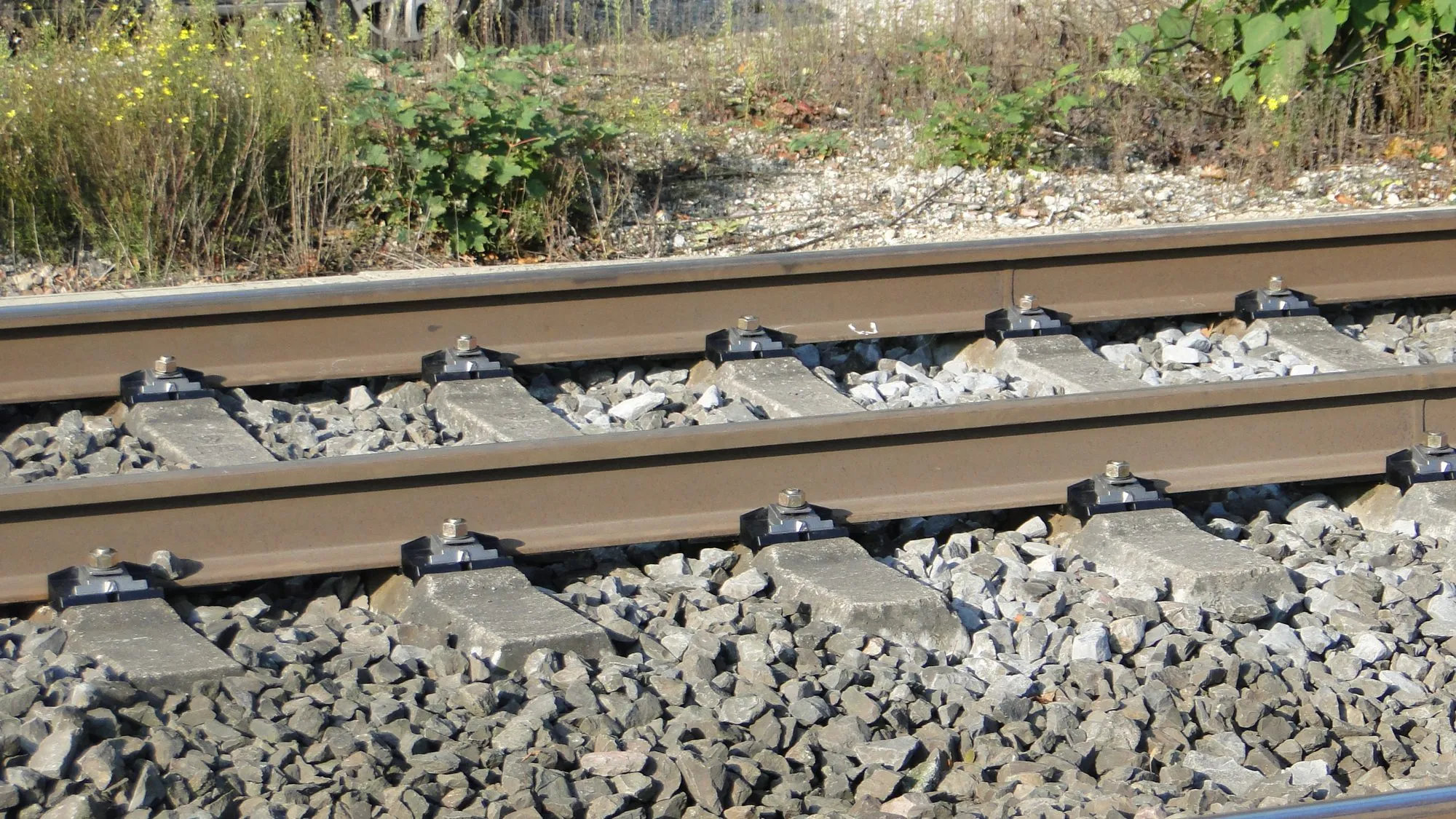
ShimLift on B70 sleepers in Cologne, Germany.